Basic Steps for Reading Electrical Diagrams
Basic Steps for Reading Electrical Diagrams
Reading Drawing Instructions
Drawing instructions include a drawing catalog, technical specifications, component lists, and construction instructions. When reading a drawing, first read the drawing instructions to understand the design content and construction requirements. This helps you understand the general design and grasp the key points.
Reading Circuit Diagrams
A circuit diagram is a simplified diagram based on the requirements of the electrical control system for production machinery movement. It uses nationally standardized electrical graphic and text symbols and details the connections of all the basic components of a circuit, equipment, or complete set of equipment, following the operating sequence of electrical equipment and appliances, regardless of their actual locations.
Circuit diagrams fully convey the purpose, function, and operating principles of electrical equipment and appliances, and serve as the theoretical basis for the installation, commissioning, and maintenance of electrical circuits.
Principles to Follow When Reading Circuit Diagrams. The following principles should be followed when reading circuit diagrams:
- Circuit diagrams are generally divided into three parts: power circuit, main circuit, and auxiliary circuit. ① The power circuit should be drawn horizontally. The three-phase AC power supply phase sequence, L1, L2, and L3, should be drawn from top to bottom. The neutral conductor (N) and protective ground conductor (PE) should be drawn below the phase conductors. The DC power supply's "+" terminal should be drawn at the top, and the "-" terminal at the bottom. The power switch should be drawn horizontally.
② The main circuit refers to the power supply receiving power and the branch circuits for control and protective devices. It consists of the main fuse, the main contacts of the contactor, the thermal element of the thermal relay, and the motor. The current flowing through the main circuit is the operating current of the motor, which is relatively high. The main circuit diagram should be drawn on the left side of the circuit diagram and perpendicular to the power circuit.
③ The auxiliary circuit generally includes the control circuit that controls the operating status of the main circuit; the indicator circuit that displays the operating status of the main circuit; and the lighting circuit that provides local illumination for machine tools. It consists of the contacts of the main control device, the contactor coil and auxiliary contacts, the relay coil and contacts, indicator lights, and lighting. The current flowing through the auxiliary circuit is relatively low, generally not exceeding 5A. When drawing auxiliary circuit diagrams, they should be drawn on the right side of the circuit diagram. Energy-consuming components connected to the lower power line (such as contactor and relay coils, indicator lights, and lighting) should be drawn at the bottom of the circuit diagram, while the contacts of electrical appliances should be drawn between the energy-consuming components and the upper power line. For ease of reading, the operating sequence should generally be arranged from left to right and from top to bottom.
- In circuit diagrams, the contacts of each electrical appliance are drawn according to their normal positions when the circuit is not energized or the appliance is not subjected to external forces. When analyzing the principle, the normal position of the contacts should be used as the starting point.
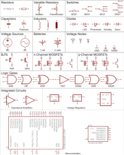
- In circuit diagrams, the actual appearance of each electrical component is not shown, but rather the nationally standardized electrical graphic symbols are used.
- In circuit diagrams, components of the same electrical appliance are not drawn together according to their actual positions. Instead, they are drawn in different circuits according to their functions in the circuit. However, their operations are interrelated and, therefore, they must be labeled with the same text symbols. If there are multiple identical electrical devices in a diagram, different numbers should be added after the device symbols to distinguish them, such as KM1, KM2, etc.
- When drawing circuit diagrams, minimize lines and avoid crossing wires. Crossing wire connections with direct electrical connections should be indicated with small black dots; crossing wires without direct electrical connections should not be indicated with small black dots.
- Circuit diagrams use the circuit numbering method, which numbers each connection in the circuit with a letter or number.
① The main circuit terminals at the power switch are numbered in phase sequence: U11, V11, W11. Then, from top to bottom and left to right, the numbers increase after each electrical component, such as U12, V12, W12; U13, V13, W13, etc. The three lead wires of a single three-phase AC motor (or device) are numbered in phase sequence: U, V, W. To avoid misunderstanding and confusion, different numbers can be used before the letters to distinguish the lead wires of multiple motors, such as 1U1V, 1W; 2U, 2V, 2W, etc.
② Auxiliary circuits should be numbered sequentially from top to bottom and left to right, following the principle of "equipotentiality." The numbers should increase after each electrical component. The control circuit number must start with 1, and the other auxiliary circuit numbers should increase by 100. For example, the lighting circuit number starts with 101; the indicator circuit number starts with 201, and so on.
- When reading a circuit diagram, first distinguish between the main circuit and the auxiliary circuit, and between the AC circuit and the DC circuit. Secondly, read the diagram in the order of main circuit first, then auxiliary circuit. When reading the main circuit, generally read from bottom to top, starting with the electrical equipment, passing through the control components, and then to the power supply. When reading the auxiliary circuits, read from top to bottom and left to right, starting with the power supply, then examining each circuit, analyzing the operating conditions of each circuit component and their control relationship to the main circuit.
Steps for reading electric traction circuit diagrams:
- Steps for reading the main circuit.
The first step is to examine electrical devices.
Understand the number of electrical devices, their types, uses, wiring methods, and various requirements.
The second step is to understand what electrical components control the electrical devices.
The third step is to identify what other electrical devices are connected to the main circuit.
The fourth step is to examine the power supply and understand its level. By examining the main circuit, you need to understand how the electrical devices obtain power and which components the power passes through to reach the load. By examining the auxiliary circuit, you need to understand its circuit structure, the connections and control relationships between the components, the conditions under which the circuit is open or closed, and understand its operation. [Official account "Mechanical Engineering Literature Collection," an engineer's refueling station!]
- Steps for reading the auxiliary circuit.
The first step is to examine the power supply.
First, understand the type of power supply, and then determine where the power for the auxiliary circuit comes from. The second step is to understand how the auxiliary circuit controls the main circuit. The third step is to identify the relationships between the electrical components. The fourth step is to examine other electrical components.
① From the main title bar, we know that this diagram is a circuit diagram within an electrical diagram. This diagram is the control circuit diagram for an M7130 surface grinder.
② From the positional perspective, the diagram is drawn using the circuit numbering method. Circuits or branches are numbered to indicate their location. The numbering method is arranged from left to right, and the function of each branch is indicated by text.
③ From the layout perspective, the entire diagram is divided from left to right into the main circuit, control circuit, electromagnetic chuck, and lighting circuit. The layout is clear and simple, making it easy to analyze the principles and troubleshoot.
④ From the power supply perspective, the main circuit is represented using multiple lines.
⑤ Similar items are primarily arranged vertically, with horizontal drawing being used less frequently. ⑥ Symbols are arranged separately. A table below the relays indicates the location of each relay contact.
⑦ The circuit diagram uses basic circuit models, such as the bridge circuit.